UDTP pre-specification
UDTP (Up/Down Transport Protocol) is a transport layer protocol that contains mechanisms for ensuring transmission quality with guaranteed delivery in packet-based networks with an explicitly organized connection.
- bandwidth allocation with transmission latency control;
- ordered delivery of user data;
- guaranteed data delivery;
- asymmetrical (up/down) data transmission;
- multiplexing / de-multiplexing of user data;
- support of forward error correction in data transmission;
- data encryption support during transmission;
- data transfer support in the form of a file, stream or message;
- resilience to failures and changes on the network level;
- mobile users support;
- support for multicast and broadcast connections on both sides;
- no duplicates during data delivery;
- real-time and time-insensitive data transfer support in a single communication channel.
UDTP is an integrated part of IPv17 network model (see Figure 1), which differs from the reference model of open systems interconnection (ITU X. 200).
Figure 1. IPv17 network model.
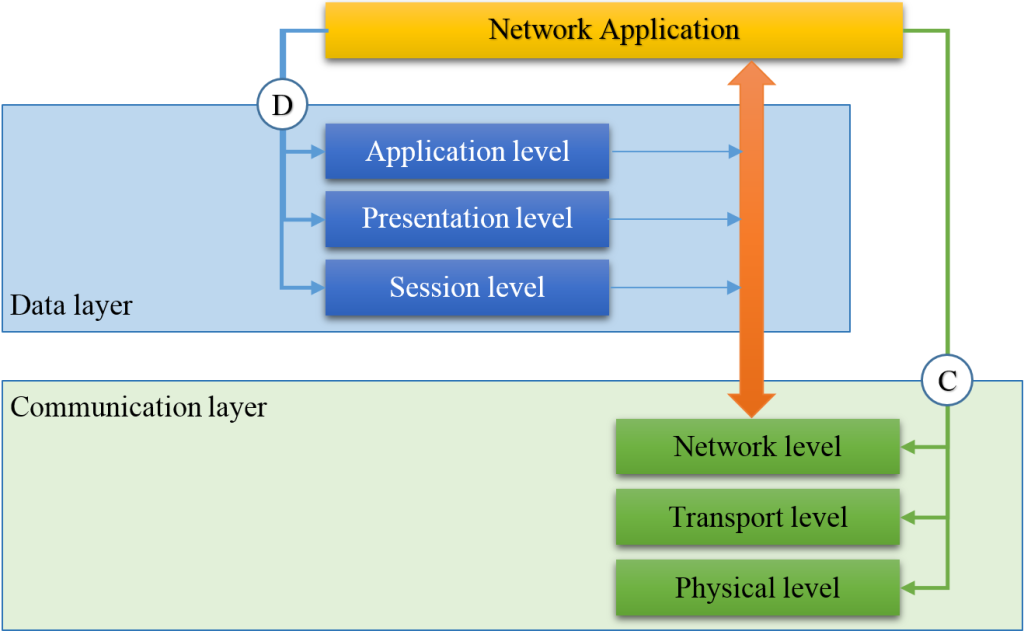
IPv17 network model consists of two layers: data layer and communication layer, each of them contains three levels and two interfaces.
The difference between IPv17 network model and ISO/OSI seven-layer reference model is that the data layer at the stage of establishing a connection defines the participants of data interaction and sets the connection parameters required for data transmission and the communication layer maintains the connection with the given parameters.
Network model — data layer, application level
- performs identification, initialization, activation and deactivation of a network application;
- synchronizes network applications activities;
- specifies a type and parameters of transmitted data.
Network model — data layer, presentation level
The presentation level coordinates a transferred data format (e.g. an order of bits transmission first of all).
Network model — data layer, session level
- searches for participants;
- identifies participants;
- establishes a connection between data exchange participants and provides a connection support;
- can tariff the connection;
- defines the FEC settings of data exchange in the communication link;
- defines cryptographic parameters the connection for data exchange;
- carries out digital rights control during data exchange.
Network model communication layer
The communication layer implements the data exchange through the transfer of data between the participants, uses for this: network, transport, physical levels and a communication interface (Protocol stack).
Network model — communication layer, network level
The network level establishes, maintains, and restores, if necessary, the route of data transfer between end systems with regard to the required connection type according to network ID (NetID).
The network level performs routing processes, for this builds, maintains, restores and removes the routes for mobile and fixed connections in a network with a static or dynamic topology.
Safety and reliability maintain routes are provided by a tabular-unbound method of establishing a route, eliminating the need for routing protocols.
Protection of the network identifier NetID from changing, blocking or deleting during the connection lifetime is provided by network level, for this inserts forcedly sender network identifier NetID in each packet of transmitted data which was selected when establishing the connection.
Network model — communication layer, transport level
The transport level solves the problem of data transferring through the transmission medium with the parameters that are set at the application level.
The transport level generates a deterministic access discipline to the transmission medium, implements, according to the established connection between the end systems, the process of data transferring, for this fragments transmitted data into data packets, transmits the data packets to the communication channel in the form of packets and receives packets from the communication channel, processes the data packets and assembles the received data packets in the form of file, stream or message.
The discipline of wired or wireless communication channels of the transmission medium allows for the data transfer settings.
Network model — communication layer, physical level
Physical level activates, maintains and deactivates a data transmission channel. The physical level implements access discipline to the transmission medium, determines tension levels and synchronizes changes of tensions, sets the transmission rate of messages, performs error protection methods, encryption methods (if necessary), modulation methods, and mechanical connections and other similar functions.
UDTP basic principles
- network ID – NetID,
- transmission mechanism – NetDMA,
- a method of data transmission quality assurance – BrD&J.
The data structure of UDTP — NetID
NetID is a user identifier.
Within IPv17 network environment, UDTP takes a network identifier (NetID) from the network entity and performs NetID registration procedure in the switching node.
- no attributes,
- one attribute, for example, PIN,
- two attributes, that
- two attributes and the attributes confirmation from an external source.
Network identifier (NetID) includes the number, name, and alias of a user. The size of network ID (NetID) can not be more than 256 octets and may have the following structure:
struct NetID {
  uint64 type:4,
         number:60;
  char[127]  *name;
  char[115]  *nic;
  uint32 crc32;
}
NetDMA data transfer mechanism
Serial transmission using the NetDMA is based on the method of dynamic time multiplexing with a changed order of the header and the body of the data packet and it is called “body forward”.
The formation of data packets allows stopping transmission of the packet body into the communication channel at any point of time maintaining the integrity of data delivery. The integrity of the data packet delivery is based on a verification code (CRC-32).
Data packet
The data packet is a container for data transfer. The data packet consists of a body and a header. The packet body contains the payload of the transmitted data and the header contains service information including information about the integrity of transmitted data.
A packet transmission is carried out in two stages. Firstly, a packet body is sent into a channel, and then the packet header with a gap. The header contains information about the integrity of the transfer packet body, which includes the length of the transmitted part of the body and the verification code (CRC-32).
The packet body has a variable length, and the packet header has a fixed length depending on the type of the header.
Data packets transmission
This paragraph is skipped because it is in a process of patenting.
NetDMA method implementation
NetDMA is implemented as a driver and uses the DMA device that is available for each processor or microcontroller but differs because it uses DMA not only for data transferring but also directly for forming a data packet, freeing the CPU from this task. This implementation significantly reduces the load on the CPU while transmission of data packets.
BrD&J mechanism of data transmission quality support
UDTP supports BrD&J mechanism (Bitrate, Delay & Jitter) to establish data transfer quality parameters, including bandwidth allocation, specifies the type of delay and maintenance the delay variation (jitter) within a predetermined range.
- bandwidth allocation for the connection
- setting latency control mode while data transfer.
Bandwidth allocation
The bandwidth allocation determines how many bits must be transmitted per time unit. Bandwidth should be measured by bps (bit per second).
Type of delay
Within the transmission cycle or without regard to the transmission cycle.
The first one is used for real-time traffic, the other one is used for time-insensitive traffic.
“Time axis”
UDTP creates or uses a “Time axis” for the purpose of forming a transmission rate which is predetermined by an application. “Time axis” is a transfer of a predetermined synchronizing sequence in the form of “Ping” packet or “Sync Code” to establish the starting point of the transmission cycle.
The cycle value is set by Channel_time_loop parameter which is in the configuration file.
- between user’s applications;
- between points that organize the physical communication channel.
The first mode may be used to perform “Time axis” synchronization function between user’s applications when the connection is established by IPv4 and IPv6 infrastructure. The second mode may be used for establishing IPv17 infrastructure connection.
The formation of the “Time axis”
- to allocate bandwidth for the connection,
-
to set a latency control mode during data transfer,
for that cyclically generates a “time axis” synchronizing sequence for the purpose of implementing the mechanism for bandwidth allocation and latency control with guaranteed jitter for specified limits.
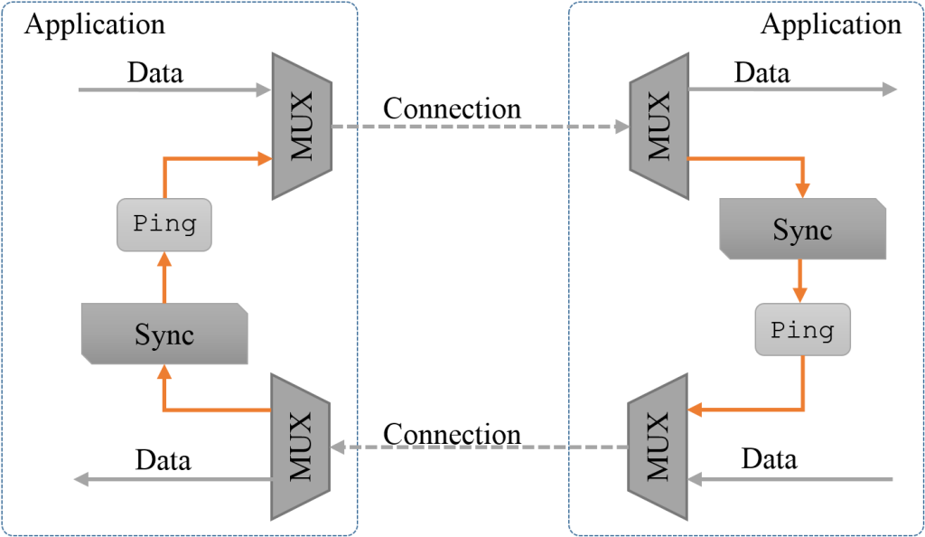
“Time axis” is formed by the periodic sending a special Ping-packet.
Figure 2. “Time axis” mode of the interface.
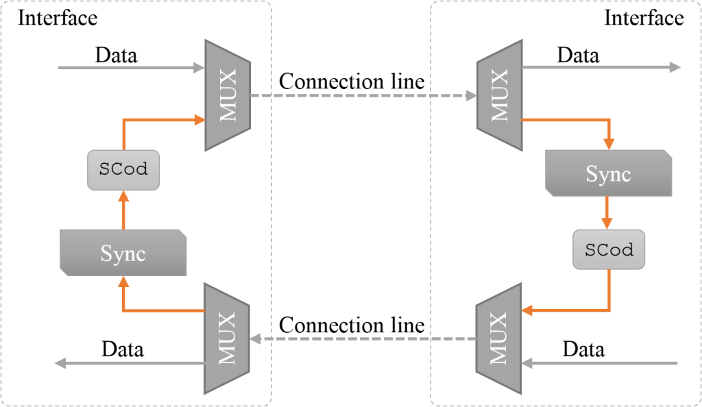
Figure 3. “Time axis” mode of the applications.
The allocation (reservation) of bandwidth is performed only during the data transmission at the connecting moment. Requested resources are released upon completion of the connection.
The network topology changes should lead to the restoration of the transmission channel, without a request for the application to close the channel.
The user’s transition between the communication nodes (handover mode) may result in the registration of the network identifier at the other communication node, but it is allowed sending registration data between communication nodes.
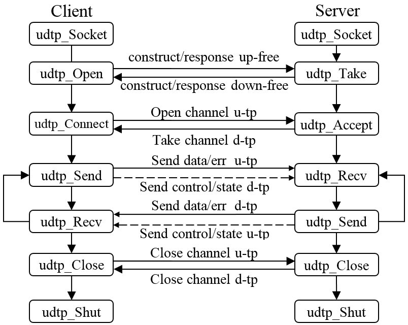
Client/server relationship
Client/server relationship chart is presented (see Figure 4).
Figure 4. Client/server relationship.
UDTP fields
NetID и UDTP
Figure 5. First packet – connection establishing.
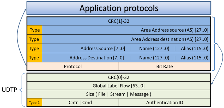
Figure 6. Second and next packets – data transfer.

Data transfer by UDTP
Data transmission recovery
Data transfer may be accompanied by losses. UDTP can implement lost data recovery by re-transmitting of a part of data or organizing a service packet with proactive FEC error codes. Transport protocol determines a recovery method.
Re-transmission
UDTP can arrange packets re-transmission by accepting a confirmation attribute of each received packet or of each packet with detected losses.
UDTP allows data transfer without receiving a confirmation attribute of the accepted data packet.
Data re-transmission uses an auxiliary connection. Organizing of packet re-transmission allows to stop data transmission on the primary connection or without stopping but using a different transmission rate within the overall prescribed bandwidth in the channel.
The size of the data packet to repeat is determined by two points that obtained in “Border file” field while receiving ‘i’ and ‘i+1’ data packets. The value of the two points is transmitted by two headers in auxiliary and service connection.
UDTP features
- a clear indication of the used application Protocol, missing the port number and there is no possibility to change the number of the Protocol when the connection is established;
- while establishing a connection it is performed a procedure of user’s NetID identification, that
- receiving a data packet does not allocate memory to process the connection,
- establishing the connection fixes the Protocol number, transmission rate and NetID that cannot be changed while a data transition process
- and each data packet has an identification field that allows identifying packets that are transferred between the endpoints of the connection;
- four threads are created while organizing a connection: primary, service, control and statistical, up to 32 connections can be arranged between the end points;
- four streams are used for:
- data is transmitted on the primary stream,
- repetition is transmitted on the service stream,
- bandwidth control, coordinating of FEC encoding and encryption are performed on the control stream,
- channel loading data and connection data are transmitted on the statistical stream;
- direct and return channels are independent of each other and can support different transmission rates;
- the protocol has a multi-path transmission mode which is used either to improve the reliability of transmission or to increase bandwidth.